TL;DR
- Problem: Weld-seam recognition demos need more than a segmentation model. Operators also need a desktop HMI, robot-control interaction, and a 3D view that makes motion and recognition results inspectable.
- Method: Built an unofficial desktop HMI for the Hiwonder LeArm platform with Qt/C++, Python segmentation inference, and OpenGL digital-twin rendering.
- Result: Integrated image selection,
predict.pyinference, result display, slider-driven joint control, and STL-based robot visualization. Resume-backed model work improved weld-seam segmentation accuracy from 64% to 96.8%.
Demo Videos
| Weld-seam recognition | Independent joint slider control |
|---|---|
 |
 |
Original videos:
Open-Source Repository and Asset Boundaries
Project repository: https://github.com/Bill-xing/HMI
The project code is open-source. The weld-seam dataset, trained model weights, and LeArm STL assets have separate distribution boundaries. This page keeps the engineering details from the README and the technical document, and all important figures have been moved into site static assets so the English page does not depend on local export paths.
Project Overview
HMI is an unofficial desktop control application for the Hiwonder LeArm robotic arm platform. It is used for weld-seam recognition, UNet semantic segmentation inference, and slider-driven digital-twin joint-control demos. The Qt/OpenGL robot visualization work references eagleqq/Robot3D, and the UNet training, prediction, and mIoU evaluation workflow references bubbliiiing/unet-pytorch. This project adapts those ideas to LeArm, integrates the Qt HMI, launches Python inference from the desktop application, and validates the digital-twin control loop.
| Module | Key Content |
|---|---|
| Qt/C++ HMI | logon, secinterface, mainwindow, and seamtest UI and business logic |
| Recognition inference | predict.py is launched through QProcess; the default weight is model_data/seam_unet.pth |
| Dataset and training | Self-collected weld-seam dataset; json_to_dataset.py converts LabelMe JSON annotations into VOC masks |
| Digital twin | DDR6RobotWidget loads base_link.STL through link_5.STL and renders them with modified DH parameters |
| Runtime paths | runtime_paths.cpp centralizes project-root discovery, Python environment discovery, and output-path handling |
| Local configuration | scripts/hmi_local_env.example.sh is only a machine-local path template; real local config is ignored |
Asset Boundaries
| Asset | Status |
|---|---|
| Repository code | Open-source at Bill-xing/HMI |
| Weld-seam dataset | Self-collected and not committed to Git; documented as CC BY 4.0 |
| Self-trained UNet weight | Default filename seam_unet.pth; excluded from Git history and documented as Apache License 2.0 |
| LeArm STL model files | Not redistributed and no redistribution rights are granted; local demos require authorized STL files |
| Default login | Demo credentials are username: admin and password: admin; this is only for UI-flow demonstration |
References and Licensing Boundaries
Third-party sources and notices are documented in THIRD_PARTY_NOTICES.
- bubbliiiing/unet-pytorch: main reference for UNet training, prediction, and mIoU evaluation. The upstream project uses the MIT License.
- eagleqq/Robot3D: main reference for Qt/OpenGL robot visualization, STL loading, and joint control.
- LeArm STL/structure model files: this repository only documents the adaptation and expected filenames; it does not provide STL files.
- Model weight:
model_data/seam_unet.pthis trained for this project scenario and is not committed to Git by default.
The repository does not declare one unified license for all content. Before public release, code, STL resources, and third-party dependency license conditions should still be checked. The dataset and model-weight licenses are documented separately.
Detailed Technical Architecture Notes
Robot Digital-Twin HMI for Weld-Seam Recognition: Technical Document
1. Document Scope
This document is normalized from the thesis, the HMI source tree, and the supplementary implementation notes. It focuses on engineering implementation rather than restating the thesis text. The coverage includes weld-seam semantic segmentation, the Qt/C++ HMI, serial-port control, OpenGL digital-twin rendering, module coupling, runtime boundaries, and validation methods.
2. Overall Architecture
2.1 System Layers
The system is organized into four main layers:
flowchart TB
    User[Operator] --> GUI[Qt/C++ HMI]
    GUI --> Login[Login and module selection]
    GUI --> SeamUI[Weld-seam recognition window: seamtest]
    GUI --> ControlUI[Robot-control window: MainWindow]
    ControlUI --> Serial[QSerialPort serial communication]
    ControlUI --> Twin[DDR6RobotWidget digital-twin view]
    SeamUI --> QProc[QProcess launches Python inference]
    QProc --> PyPredict[predict.py]
    PyPredict --> Model[UNet/VGG16 weight: seam_unet.pth]
    PyPredict --> Result[segmented_image.png]
    SeamUI --> EventBus[globaleventbus singleton]
    EventBus --> ControlUI
    Twin --> STL[res/binary/*.STL]
| Layer | Main Components | Responsibility |
|---|---|---|
| UI layer | logon.ui, secinterface.ui, mainwindow.ui, seamtest.ui |
Login, module entry, image display, serial configuration, slider control |
| Business layer | logon.cpp, secinterface.cpp, mainwindow.cpp, seamtest.cpp |
Flow scheduling, signal-slot wiring, serial command assembly, inference process management |
| Algorithm layer | predict.py, unet.py, nets/, utils/, train.py |
Model training, inference, mIoU evaluation, data augmentation |
| Rendering layer | rrglwidget.cpp, ddr6robotwidget.cpp, stlfileloader.cpp |
OpenGL initialization, binary STL parsing, robot joint transforms, interactive rendering |
| Runtime support | runtime_paths.cpp, scripts/, docs/reproduction/ |
Project-root discovery, Python environment lookup, output directory handling, packaging support |
2.2 Source Tree
Key files in HMI:
HMI/
├── HMI.pro                         # Qt qmake project file
├── main.cpp                        # Application entry and --self-test entry
├── logon.*                         # Login window
├── secinterface.*                  # Secondary module-selection window
├── mainwindow.*                    # Robot control and serial communication window
├── seamtest.*                      # Weld-seam recognition window
├── globaleventbus.*                # Recognition-success event bus
├── runtime_paths.*                 # Runtime path, Python environment, and output path lookup
├── rrglwidget.*                    # Base OpenGL rendering widget
├── ddr6robotwidget.*               # LeArm digital-twin rendering widget
├── stlfileloader.*                 # STL file parsing and drawing
├── predict.py                      # Single-image inference entry
├── unet.py                         # Inference wrapper
├── train.py                        # Training script
├── get_miou.py                     # mIoU evaluation entry
├── json_to_dataset.py              # LabelMe JSON to segmentation dataset conversion
├── nets/                           # UNet/VGG16 network definitions
├── utils/                          # Dataloader, loss, training, and metric utilities
├── model_data/                     # Model-weight directory, default: seam_unet.pth
├── res/binary/                     # LeArm STL directory, not publicly redistributed
├── docs/                           # Dataset, weight, reproduction, and packaging notes
└── scripts/                        # Local environment and packaging scripts
2.3 Build and Dependency Model
The Qt project is managed by HMI.pro.
| Configuration | Content |
|---|---|
| Qt modules | core, gui, widgets, serialport, opengl |
| C++ standard | C++17 |
| Python integration | PYTHON_HOME and PYTHON_VERSION provide Python headers and library paths |
| macOS rpath | Points to PYTHON_HOME/lib and the bundled Resources/python/lib directory |
| Qt resources | res.qrc, including UI image resources |
| Source files | Control, recognition, event bus, runtime-path, OpenGL, and STL-loading files |
Python dependencies are recorded in requirements.txt.
| Dependency | Version | Purpose |
|---|---|---|
torch |
1.10.2 | Model training and inference |
torchvision |
0.11.3 | Vision model and preprocessing ecosystem |
opencv-python |
4.1.2.30 | Resize, color conversion, post-processing |
Pillow |
8.3.1 | Image loading, saving, and blending |
numpy |
1.19.2 | Array computation |
labelme |
3.16.7 | Annotation data processing |
matplotlib |
3.3.4 | Training curves and evaluation visualization |
tqdm |
4.60.0 | Training progress bars |
3. Weld-Seam Semantic Segmentation
3.1 Technical Flow
The recognition module uses a U-Net style semantic segmentation pipeline. The complete process is: collect weld-seam images under multiple viewpoints and lighting conditions, annotate the seam region with LabelMe, convert JSON annotations into a VOC-style segmentation dataset, train a VGG-UNet model, evaluate mIoU, and call predict.py from the HMI for single-image inference.
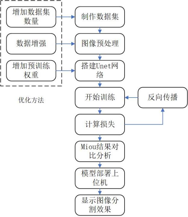
Figure 2-1. U-Net semantic segmentation workflow.
3.2 Data Collection and Annotation
The weld-seam task uses pixel-level labels. Unlike object detection, which annotates rectangular boxes, semantic segmentation assigns a category to every pixel. The thesis workflow uses LabelMe polygons to outline weld-seam boundaries.
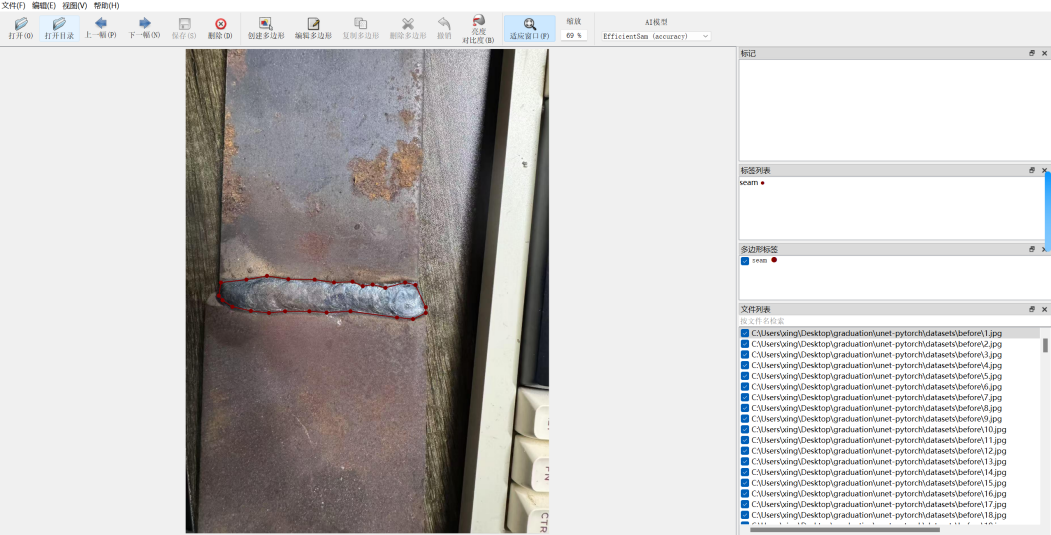
Figure 2-2. LabelMe annotation example.
The dataset is binary:
| Class Index | Class Name | Meaning |
|---|---|---|
| 0 | _background_ |
Background |
| 1 | seam |
Weld seam |
The public dataset notes record the following split:
| Split | Count |
|---|---|
| train | 845 |
| val | 94 |
| trainval | 939 |
| test | 0 |
VOC-style layout:
VOC2007/
├── JPEGImages/                 # Original images
├── SegmentationClass/          # Segmentation masks
└── ImageSets/
    └── Segmentation/
        ├── train.txt
        ├── val.txt
        └── trainval.txt
3.3 LabelMe JSON to VOC Masks
The conversion script is json_to_dataset.py. Its core logic:
- Scan LabelMe JSON files under
datasets/before/. - Read the source image from either the JSON
imageDatafield or theimagePathfield. - Use
labelme.utils.shapes_to_labelto rasterize polygon annotations into a pixel label matrix. - Build the class mapping:
_background_ -> 0,seam -> 1. - Save the source image to
datasets/JPEGImagesand the mask todatasets/SegmentationClass.
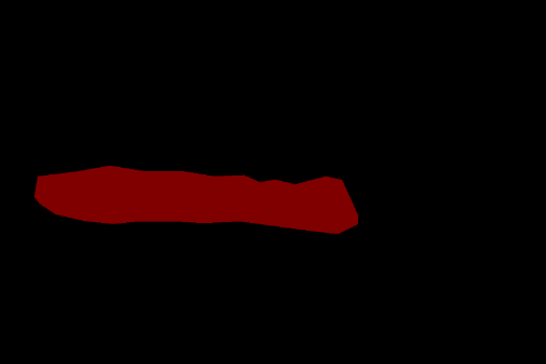
Figure 2-3. Generated mask image.
Two implementation constraints matter:
- Masks must store class indices, not RGB colors. During training,
utils/dataloader.pyconverts them into one-hot labels. - Label resizing must use nearest-neighbor interpolation so continuous interpolation does not corrupt class indices.
3.4 Network Structure
3.4.1 Base U-Net
U-Net consists of an encoder, a decoder, and skip connections. The encoder progressively downsamples features from local details to global semantics. The decoder upsamples them to recover spatial resolution. Skip connections concatenate encoder-side detail features with decoder-side semantic features, which improves edge recovery.
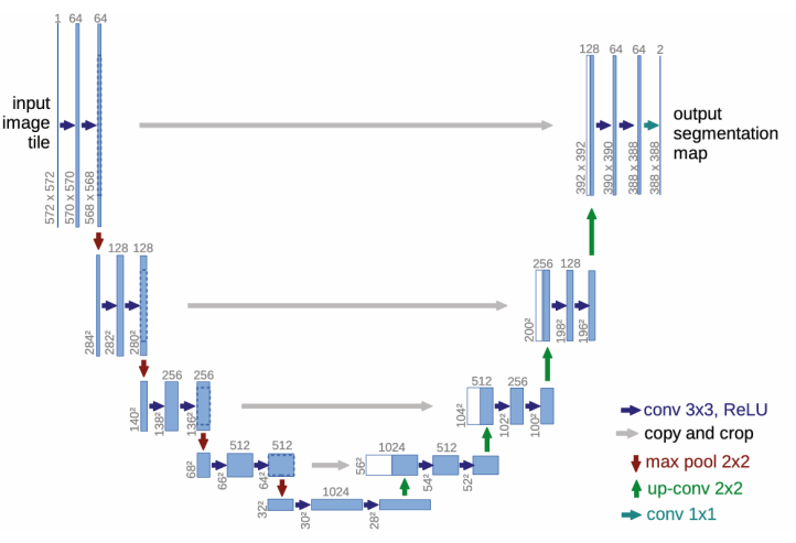
Figure 2-8. U-Net architecture.
3.4.2 VGG-UNet
The final model uses backbone = "vgg". Its encoder uses VGG16 to extract multi-scale features. The decoder uses unetUp modules to recover spatial resolution and concatenate same-scale encoder features. This structure works better than the initial U-Net variant for the small-sample weld-seam segmentation scenario.
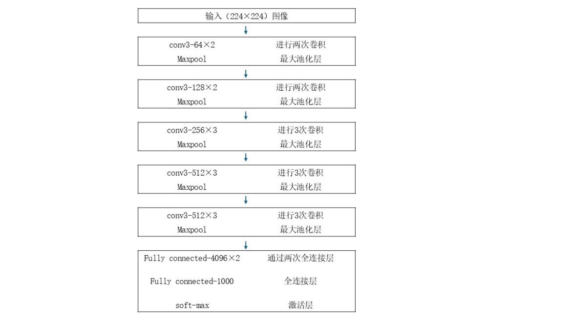
Figure 2-10. VGG16 network structure.
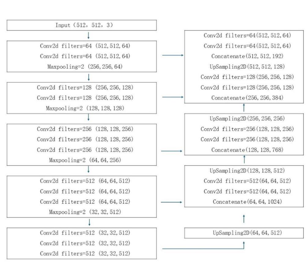
Figure 2-11. VGG-UNet structure.
Implementation notes in nets/unet.py:
- The
Unetclass switches between a VGG16 encoder and the original U-Net encoder through thebackboneargument. - In VGG mode, the encoder outputs five feature levels:
feat1throughfeat5. - The decoder executes
up_concat4,up_concat3,up_concat2, andup_concat1. - The final layer generates two-class pixel logits: background and weld seam.
Execution order:
up4 = up_concat4(feat4, feat5)
up3 = up_concat3(feat3, up4)
up2 = up_concat2(feat2, up3)
up1 = up_concat1(feat1, up2)
final = output_layer(up1)
The structure fits weld-seam boundary segmentation because pretrained VGG16 features improve convergence and generalization on a small dataset, U-Net skip connections preserve edge and texture detail, and binary output keeps the task focused on seam versus background.
3.5 Training Configuration
The training entry is train.py.
| Parameter | Current Value | Notes |
|---|---|---|
Cuda |
True |
Prefer GPU |
num_classes |
2 |
Background + weld seam |
backbone |
"vgg" |
VGG16 encoder |
pretrained |
True |
Initialize from pretrained weights |
model_path |
model_data/seam_unet.pth |
Load or fine-tune an existing weight |
input_shape |
[512, 512] |
Network input size |
Freeze_Epoch |
50 |
Freeze-stage training target |
Freeze_batch_size |
2 |
Freeze-stage batch size |
Freeze_lr |
1e-4 |
Freeze-stage learning rate |
UnFreeze_Epoch |
100 |
Unfreeze-stage training target |
Unfreeze_batch_size |
2 |
Unfreeze-stage batch size |
Unfreeze_lr |
1e-5 |
Unfreeze-stage learning rate |
dice_loss |
True |
Use Dice Loss for small-object segmentation |
focal_loss |
False |
Not enabled in the current configuration |
optimizer |
Adam | Adaptive optimizer |
lr_scheduler |
StepLR, gamma=0.96 | Learning-rate decay per epoch |
num_workers |
4 |
Dataloader worker count |
Training flow:
flowchart LR
    ReadList[Read train.txt / val.txt] --> Dataset[UnetDataset]
    Dataset --> Aug[Augmentation and preprocessing]
    Aug --> Loader[DataLoader]
    Loader --> Forward[Forward pass]
    Forward --> Loss[CE Loss + Dice Loss]
    Loss --> Backward[Backpropagation]
    Backward --> Adam[Adam update]
    Adam --> Save[Save logs/ep*-loss*.pth]
3.6 Augmentation and Preprocessing
utils/dataloader.py implements training augmentation in get_random_data(). Validation only performs aspect-ratio preserving resize and center padding.
| Augmentation | Implementation | Purpose |
|---|---|---|
| Aspect-ratio jitter | jitter=.3 with random target aspect ratio |
Improve robustness to viewpoints and seam shapes |
| Random scale | scale from 0.25 to 2 |
Improve scale robustness |
| Horizontal flip | 50% probability | Improve direction invariance |
| Random placement | Paste the resized image onto a 512x512 gray canvas | Simulate target position variation |
| HSV jitter | Random hue, saturation, and value shifts | Improve robustness under lighting variation |
Image preprocessing:
- Use
cvtColor()to ensure RGB input. - Use
resize_image()to fit 512x512 while preserving aspect ratio; pad the rest with gray. - Apply
preprocess_input()normalization. - Convert
HWCtoCHW, then add the batch dimension.
Label processing:
- Resize masks with nearest-neighbor interpolation.
- Map out-of-range pixels to
num_classes. - Use
np.eye(num_classes + 1)for one-hot labels used by Dice/F-score metrics.
3.7 Losses and Metrics
The default training loss is cross-entropy plus Dice Loss. Dice Loss is useful for small-object segmentation because the weld seam occupies a small image area.
DiceLoss = 1 - \frac{2|X \cap Y|}{|X| + |Y|}
X is the predicted region and Y is the ground-truth annotation.
The evaluation metrics are pixel-level IoU, PA Recall, and Precision:
PA\_Recall = \frac{TP}{TP + FN}
Precision = \frac{TP}{TP + FP}
IoU = \frac{TP}{TP + FP + FN}
| Symbol | Meaning |
|---|---|
| TP | Weld-seam pixels correctly recognized |
| FP | Background pixels wrongly predicted as weld seam |
| FN | Actual weld-seam pixels missed by the model |
| TN | Background pixels correctly excluded |
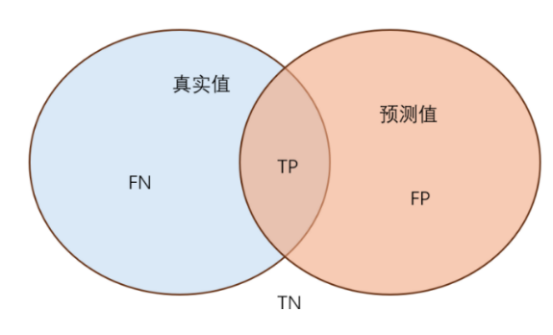
Figure 2-9. IoU diagram.
3.8 Optimization Results
The recorded optimization path has three main stages:
- Switching from the original U-Net to VGG-UNet improved segmentation accuracy from about 64% to about 87%.
- Adding VGG16 pretrained weights improved it from about 87% to about 89%.
- Expanding the dataset from 30 images to 939 images reached about 96.8% accuracy.
| VGG-UNet mIoU | Original U-Net mIoU |
|---|---|
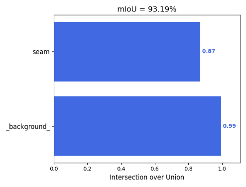 |
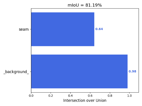 |
Figures 2-12 and 2-13. Model-structure comparison.
| Without Pretraining | With Pretraining |
|---|---|
 |
 |
Figures 2-14 and 2-15. Pretraining comparison.
| 30-Image Dataset | 939-Image Dataset |
|---|---|
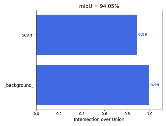 |
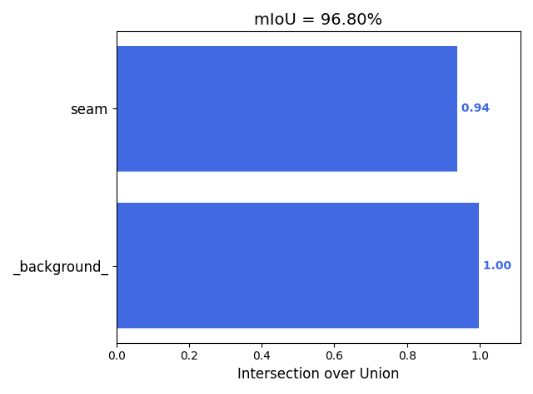 |
Figures 2-16 and 2-17. Dataset expansion comparison.
Before-and-after segmentation comparison:
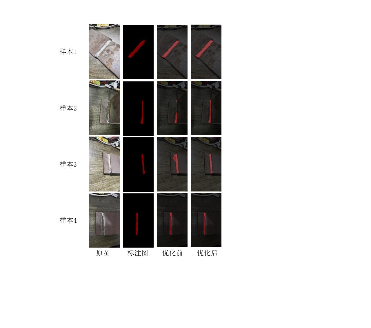
Figure 2-18. Semantic segmentation comparison.
3.9 Inference Flow
The inference entry is predict.py, and the wrapper class is Unet in unet.py.
| Configuration | Default |
|---|---|
model_path |
model_data/seam_unet.pth |
num_classes |
2 |
backbone |
vgg |
input_shape |
[512, 512] |
mix_type |
1, blend original image and segmentation result |
cuda |
automatically determined |
The HMI calls the Python script through QProcess:
seamtest::processImage(imagePath)
  -> QProcess starts predict.py
  -> predict.py loads Unet
  -> detect_image(image)
  -> save segmented_image.png
  -> seamtest reads and displays the result
The result displayed in the HMI:
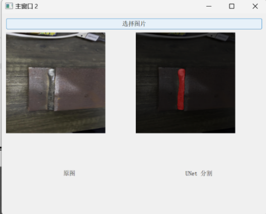
Figure 2-19. HMI recognition result.
4. Qt/C++ HMI Control Module
4.1 From PyQt Prototype to C++ Qt
The project initially explored a PyQt-based prototype, but the final HMI was refactored into C++ Qt. The refactor has practical reasons:
- Qt Designer UI files, C++ signal-slot wiring, and OpenGL widgets can be integrated directly.
QSerialPortprovides convenient serial-port scanning and byte-array sending.QGLWidgetand legacy OpenGL immediate mode are easier to integrate with the Robot3D reference code.- qmake plus platform deployment tools can produce desktop application bundles.
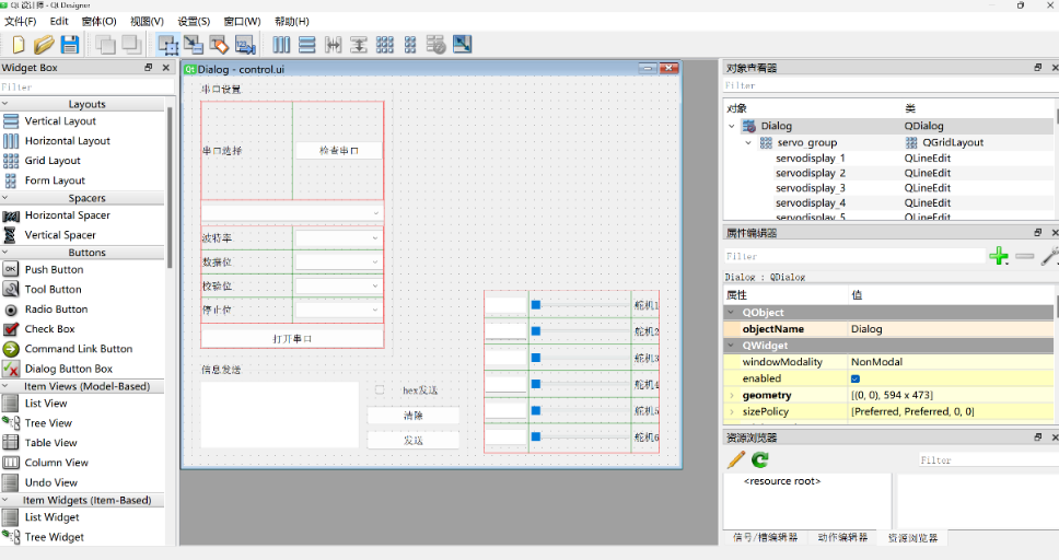
Figure 3-2. Qt Designer interface layout.
4.2 Application Flow and Windows
main.cpp starts the Secinterface window in normal mode. The --self-test argument enters an automated smoke-test mode.
Main UI classes:
| Class | UI File | Responsibility |
|---|---|---|
Logon |
logon.ui |
Login and remember-password checkbox |
Secinterface |
secinterface.ui |
Secondary module selection |
MainWindow |
mainwindow.ui |
Serial communication, robot control, digital twin |
seamtest |
seamtest.ui |
Image selection, inference process, result display |
Login logic:
- Default credentials:
username: admin,password: admin. - The remember-password checkbox is saved into
config.json. - A successful login emits the
login()signal. Secinterfacereceives the signal and switches to the function-selection window.
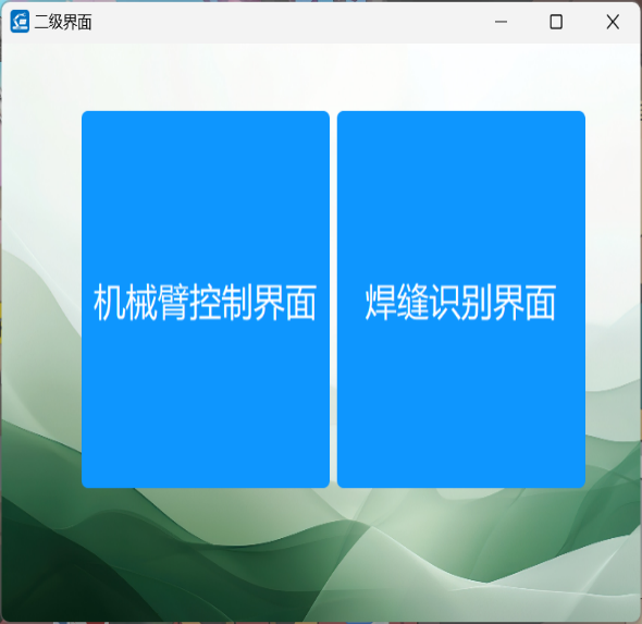
Login and module-selection windows:
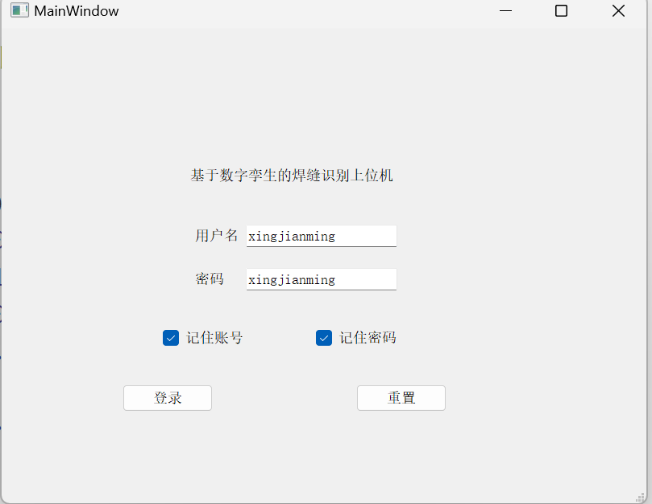
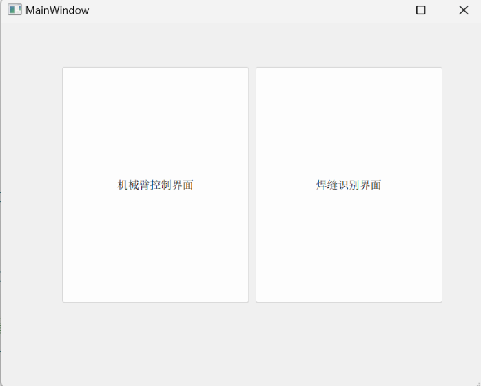
UI design drafts:
| Login UI Design | Module Selection UI Design |
|---|---|
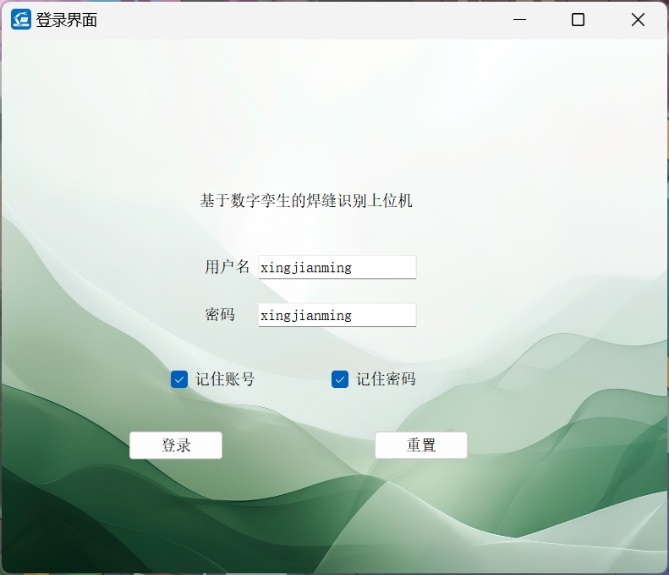 |
 |
4.3 Serial-Port Control Logic
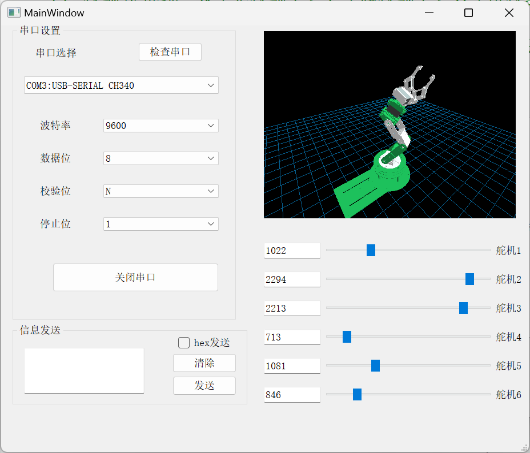
MainWindow provides serial-port scanning, parameter configuration, opening/closing the port, manual HEX sending, slider control, and robot-digital-twin synchronization.
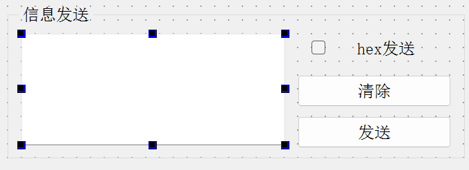
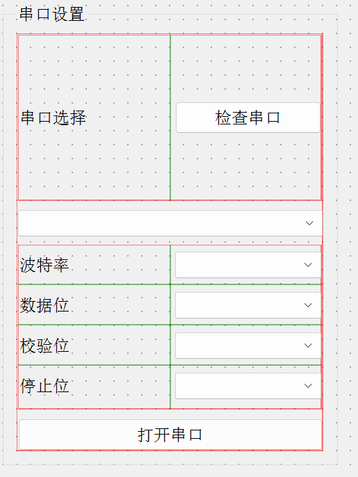
Control-window sections:
| Overview | Serial Settings | Joint Slider Area |
|---|---|---|
 |
 |
 |
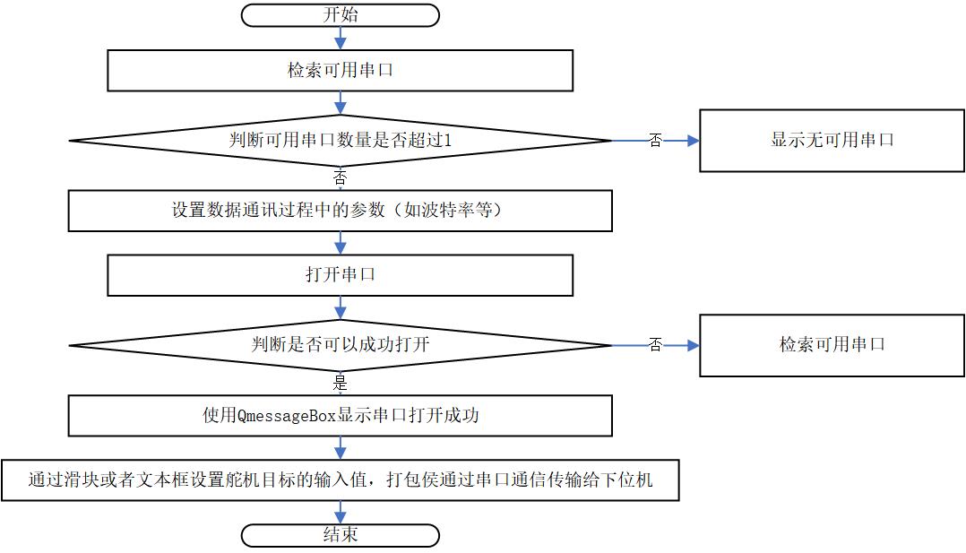
Serial-port detection:
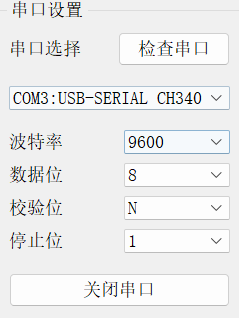
MainWindow::detectPort() refreshes available serial ports through QSerialPortInfo::availablePorts(). When a port is selected, baud rate, data bits, parity, stop bits, and flow control are configured before opening the port.
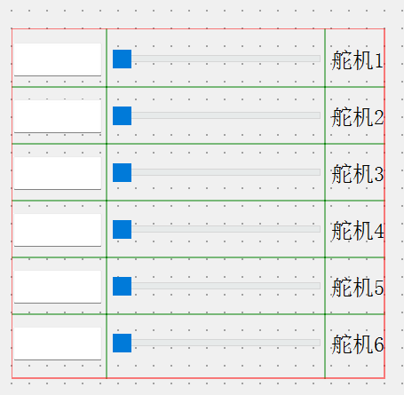
4.4 Servo Control Protocol
The LeArm servo-control area uses six sliders and six text boxes. Each slider updates the corresponding joint value, sends a serial command when the port is open, and updates the OpenGL digital-twin pose.
The command packet follows this pattern:
55 55 len cmd servo_id low_byte high_byte time_low time_high
The implementation assembles a QByteArray, converts slider values into low/high bytes, and writes it through serial->write(data).
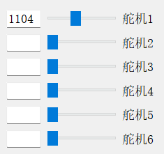
4.5 Slider to Digital-Twin Joint Mapping
Slider values are not used as joint angles directly. They are first mapped into model-space joint variables.
Important observations from the implementation:
- Sliders use Hiwonder-style servo pulse values.
DDR6RobotWidget::setJ1()throughsetJ6()update the six model joint variables.- After each update,
updateGL()refreshes the OpenGL view. - The model offsets are tuned to match the STL coordinate frames and the robot’s visual pose.
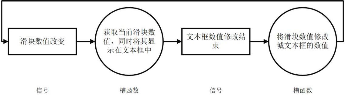
Signal-slot and slider-control diagrams:
4.6 Weld-Seam Window and Python Inference Integration
The seamtest window manages image selection and recognition.
Main flow:
- The user selects an image.
- The HMI displays the source image.
QProcessstarts the Python inference script.- The HMI waits for process completion.
- The HMI reads
segmented_image.png. - The result is displayed in the right-side preview area.
- If recognition succeeds,
seam_detect_success()is emitted.
Using QProcess keeps Python inference isolated from the C++ UI. It also avoids embedding Python model code inside the Qt process, which would make packaging and dependency handling more fragile.
4.7 Runtime Path Management
runtime_paths.cpp prevents the application from relying on a fixed working directory. It resolves:
- Project root.
- Python executable.
- Python environment path.
- Inference output path.
segmented_image.png.config.json.- STL resource directory.
The lookup order is:
- Use
HMI_PROJECT_ROOTif it is set. - Otherwise infer the project root from the application path and known project files.
- For Python, prefer
PYTHON_EXECUTABLE, then derive fromPYTHON_HOME, then fall back topython. - For outputs, prefer
HMI_OUTPUT_DIR, then fall back to a writable runtime directory.
This design is important because Qt applications behave differently when run from the build directory, from a .app bundle, or from a packaged directory.
5. Digital-Twin Module
5.1 Robot Object and Modeling Goal
The digital-twin module aims to show the LeArm robot pose in the HMI and to let the user observe the effect of each slider-controlled joint. The model is not a physics simulator; it is a visual and kinematic representation for HMI feedback.
| Robot Model | DH Coordinate Frame |
|---|---|
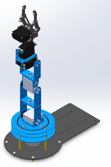 |
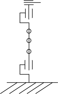 |
5.2 Modified DH Parameters
The coordinate system uses a modified DH convention.
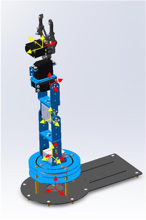
Figure 4-3. Modified DH coordinate frame.
Recorded dimensions:
d1 = 95 mm
d2 = 9.5 mm
d3 = 104 mm
d4 = 88.47 mm
d5 = 59.28 mm
Modified DH table:
| i | a(i-1) | alpha(i-1) | d(i) | theta(i) |
|---|---|---|---|---|
| 1 | 0 | 0 | d1 | 0 |
| 2 | d2 | -pi/2 | 0 | -pi/2 |
| 3 | d3 | 0 | 0 | 0 |
| 4 | d4 | 0 | 0 | -pi/2 |
| 5 | 0 | -pi/2 | d5 | -pi/2 |
| 6 | 0 | pi/2 | 0 | 0 |
DDR6RobotWidget::configureModelParams() uses rendering parameters:
mRobotConfig.d     = {0, 95.0, 0.00, 0.00, 0.00, 59.28, 0.00};
mRobotConfig.JVars = {0, 0, 90, 0, -90, 0, 0};
mRobotConfig.a     = {0, 0, -9.8, 104, 88.47, 0, 0};
mRobotConfig.alpha = {0, 0, 90, 0, 0, -90, 0};
The leading element is a placeholder, and actual joints start at index 1. a[2] = -9.8 corresponds to the small structural offset near the documented d2 = 9.5 mm, with sign and magnitude adjusted to align the STL coordinate frames.
5.3 Forward Kinematics
The single-step modified DH transform:
^{i-1}T_i =
R_X(\alpha_{i-1})
D_X(a_{i-1})
R_Z(\theta_i)
D_Z(d_i)
Matrix form:
^{i-1}T_i =
\begin{bmatrix}
\cos\theta_i & -\sin\theta_i & 0 & a_{i-1} \\
\sin\theta_i\cos\alpha_{i-1} & \cos\theta_i\cos\alpha_{i-1} & -\sin\alpha_{i-1} & -\sin\alpha_{i-1}d_i \\
\sin\theta_i\sin\alpha_{i-1} & \cos\theta_i\sin\alpha_{i-1} & \cos\alpha_{i-1} & \cos\alpha_{i-1}d_i \\
0 & 0 & 0 & 1
\end{bmatrix}
The full end-effector pose:
^0T_i = ^0T_1 \cdot ^1T_2 \cdot \ldots \cdot ^{i-1}T_i
In OpenGL rendering, the code does not build an explicit matrix object. It applies the transforms in order:
glTranslatef(a, 0.0, 0.0);
glRotatef(alpha, 1.0, 0.0, 0.0);
glTranslatef(0.0, 0.0, d);
glRotatef(theta, 0.0, 0.0, 1.0);
OpenGL’s matrix stack performs the accumulated transforms implicitly, so each link is drawn relative to the previous link.
5.4 Inverse Kinematics and Verification
The thesis derives analytic expressions for theta1 through theta6 from the homogeneous transform matrix. The core idea:
- Use the position terms to solve
theta1. - Use orientation-matrix elements to eliminate variables and solve
theta5andtheta6. - Use the combined angle
theta234for wrist orientation. - Use geometry to solve
theta2andtheta3. - Compute
theta4 = theta234 - theta2 - theta3.
Because serial robot inverse kinematics can have multiple solutions, singularities, and unreachable poses, the notes record eight candidate solutions and some NaN entries. This is consistent with analytic IK for a six-axis serial arm.
Robotics Toolbox was used to cross-check forward and inverse kinematics:
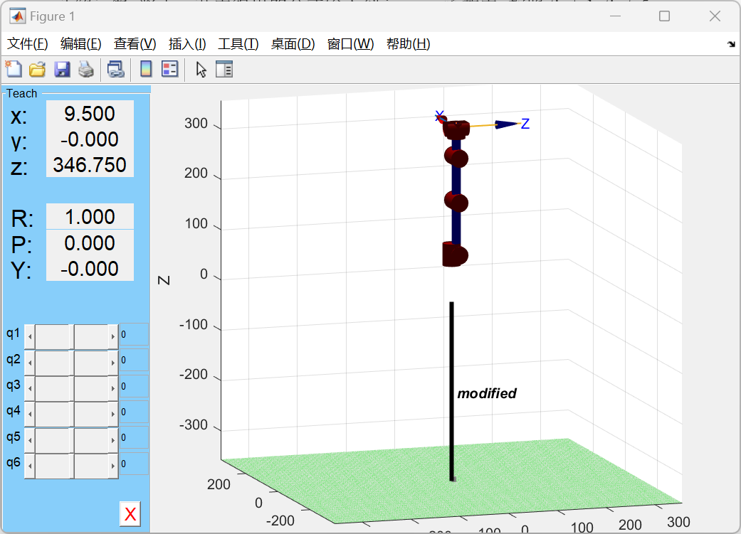
Figure 4-4. Robotics Toolbox simulation.
Forward-kinematics test data:
| Input Joint Angles | End-Effector Pose Matrix |
|---|---|
[pi/4, -2*pi/3, -2*pi/3, 0, 2*pi/3, 0] |
[[0.7891, -0.6124, 0.0474, -9.6593], [-0.4356, -0.6124, -0.6597, -9.6593], [0.4330, 0.5000, -0.7500, 15.0000], [0, 0, 0, 1.0000]] |
The inverse-kinematics test shows that T2 matches the preset T0, so the analytic inverse solution and the forward solution are consistent at the tested point.
5.5 STL Loading
Each robot link uses a binary STL file:
res/binary/
├── base_link.STL
├── link_1.STL
├── link_2.STL
├── link_3.STL
├── link_4.STL
└── link_5.STL
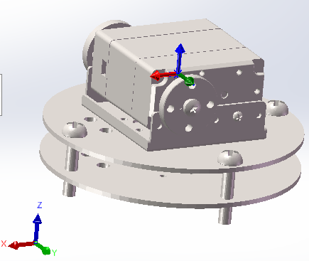
Figure 4-5. Joint part.
STLFileLoader::loadBinaryStl() parses binary STL files:
| Byte Range | Content | Size |
|---|---|---|
| 0-79 | File header | 80 bytes |
| 80-83 | Triangle count triangle_num |
4 bytes |
| Each triangle | Normal vector + three vertices + attribute field | 50 bytes |
Single-triangle layout:
| Field | Content | Size |
|---|---|---|
| normal | 3 floats | 12 bytes |
| vertex 1 | 3 floats | 12 bytes |
| vertex 2 | 3 floats | 12 bytes |
| vertex 3 | 3 floats | 12 bytes |
| attribute | Attribute byte count | 2 bytes |
The theoretical file size is:
FileSize = 84 + 50 \times N_{facet}
The code reads the file into memory and parses it with pointer offsets. This keeps the logic simple and fast for small LeArm demo models, although larger models would benefit from streaming or buffered parsing.
5.6 OpenGL Rendering Pipeline
RRGLWidget inherits from QGLWidget. Its responsibilities:
| Function | Purpose |
|---|---|
initializeGL() |
Configure lighting, depth testing, normal normalization, background color |
resizeGL() |
Set viewport and perspective projection |
paintGL() |
Overridden by subclasses for each-frame rendering |
drawGrid() |
Draw ground grid |
drawCoordinates() |
Draw world coordinate frame |
drawSTLCoordinates() |
Draw local STL coordinate frame |
setupColor() |
Configure material color |
mouseMoveEvent() |
Handle rotation, zoom, and pan |
STLFileLoader::draw() uses immediate-mode OpenGL:
glBegin(GL_TRIANGLES);
for each triangle:
    glNormal3f(normal.x, normal.y, normal.z);
    glVertex3f(vertex0.x, vertex0.y, vertex0.z);
    glVertex3f(vertex1.x, vertex1.y, vertex1.z);
    glVertex3f(vertex2.x, vertex2.y, vertex2.z);
glEnd();
This is appropriate for learning and verification, but a larger or higher-frame-rate model should move to VBO/VAO rendering to reduce CPU-to-GPU submissions.
5.7 Joint-Level Rendering
DDR6RobotWidget inherits RRGLWidget. It loads every link STL and applies matrix transforms in joint order.
Initial view parameters:
z_zoom = -500;
xRot = 30 * 16;
yRot = 45 * 16;
xTran = 0;
yTran = -200;
paintGL() clears color/depth buffers and applies the view transform:
glTranslated(0, 0, z_zoom);
glTranslated(xTran, yTran, 0);
glRotated(xRot / 16.0, 1.0, 0.0, 0.0);
glRotated(yRot / 16.0, 0.0, 1.0, 0.0);
glRotated(zRot / 16.0, 0.0, 0.0, 1.0);
glRotated(+90.0, 1.0, 0.0, 0.0);
glRotated(180.0, 1.0, 0.0, 0.0);
drawGL();
drawGL() draws base, link1, link2, link3, link4, and link5 in order. Before each link is drawn, the corresponding DH translation and rotation are applied; later links inherit the transforms from earlier joints.
Digital-twin and physical states:
| HMI State 1 | Physical State 1 |
|---|---|
 |
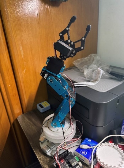 |
| HMI State 2 | Physical State 2 |
|---|---|
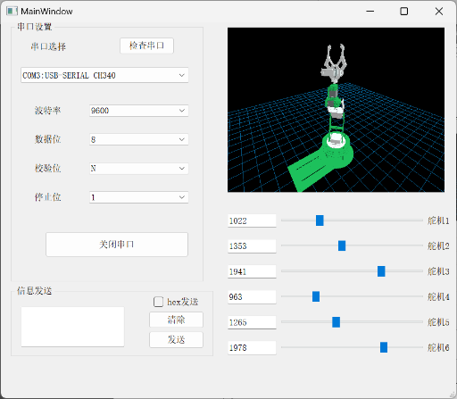 |
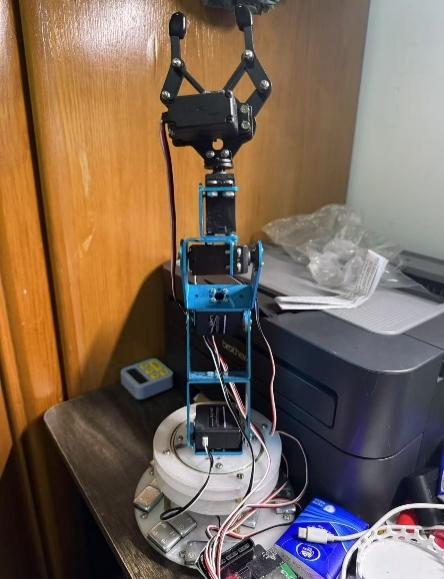 |
Figure 4-6. Digital-twin state compared with physical robot state.
5.8 Mouse Interaction
RRGLWidget::mouseMoveEvent() supports three interactions:
| Mouse Operation | Variable | Effect |
|---|---|---|
| Left drag | xRot, yRot |
Rotate view |
| Right drag | z_zoom |
Zoom view |
| Middle drag | xTran, yTran |
Pan view |
Qt stores rotation values as angle * 16, so rendering divides by 16.0 to recover degrees.
6. Module Coupling
6.1 From Recognition Success to Robot Motion
The recognition module and robot-control module are decoupled through globaleventbus.
sequenceDiagram
    participant Seam as seamtest
    participant Proc as QProcess/predict.py
    participant Bus as globaleventbus
    participant Main as MainWindow
    participant Twin as DDR6RobotWidget
    participant Serial as QSerialPort

    Seam->>Proc: processImage(imagePath)
    Proc-->>Seam: exitCode == 0
    Seam->>Seam: Check segmented_image.png
    Seam->>Bus: emit seam_detect_success()
    Bus->>Bus: onSeamDetectionSuccess()
    Bus-->>Main: emit seamDetectionSuccess()
    Main->>Main: move_Learm()
    Main->>Twin: Update six sliders and JVars
    Main->>Serial: Send servo command if port is open
globaleventbus is a QObject singleton:
static globaleventbus* getInstance() {
    static globaleventbus instance;
    return &instance;
}
seamtest connects recognition success to the event bus:
connect(this, SIGNAL(seam_detect_success()),
        globaleventbus::getInstance(),
        SLOT(onSeamDetectionSuccess()));
MainWindow::initSerialPort() listens to the global signal:
connect(globaleventbus::getInstance(),
        SIGNAL(seamDetectionSuccess()),
        this,
        SLOT(move_Learm()));
This publisher-subscriber design avoids making seamtest hold a direct MainWindow pointer. The recognition window and control window can remain independent in lifecycle and display logic.
6.2 Preset Motion Pose
After successful recognition, MainWindow::move_Learm() sets six sliders to fixed values:
| Servo | Target Slider Value |
|---|---|
| 1 | 1015 |
| 2 | 1162 |
| 3 | 1757 |
| 4 | 1647 |
| 5 | 1412 |
| 6 | 1640 |
Changing the sliders triggers the existing valueChanged chain, so the text boxes, digital-twin joint angles, and serial packets are all updated through the same path. move_Learm() does not need to call OpenGL refresh or serial sending directly.
7. Runtime Resource Boundaries
The page intentionally keeps resource and path boundaries instead of a command-style runbook. Local reproduction depends on Qt 5, a C++17 toolchain, a Python environment compatible with requirements.txt, the trained model_data/seam_unet.pth weight, a test weld-seam image, and authorized LeArm STL files. Machine-specific paths should be derived from scripts/hmi_local_env.example.sh and kept out of Git.
Key environment variables:
| Variable | Purpose |
|---|---|
HMI_PROJECT_ROOT |
Explicit HMI project root |
PYTHON_EXECUTABLE |
Python executable used by inference |
PYTHON_HOME |
Python/Conda environment root for Python C API and linker paths |
PYTHON_VERSION |
Python version, such as 3.9 |
HMI_OUTPUT_DIR |
Output directory for segmented_image.png and config.json |
HMI_TEST_IMAGE |
Input image for self-test mode |
HMI_INCLUDE_LOCAL_STL_ASSETS |
Whether private packages include local STL files |
main.cpp provides a --self-test mode. It checks:
- Whether
predict.pyexists. - Whether
model_data/seam_unet.pthexists. - Whether
HMI_TEST_IMAGEis set and points to a file. - Whether the default
admin/adminlogin emits theloginsignal. - Whether
MainWindowcan initialize. - Whether
seamtest::processImage()can generatesegmented_image.png. - Whether
seam_detect_successis emitted.
Offscreen mode can limit OpenGL context behavior, so the self-test mainly verifies recognition and UI initialization, not full 3D rendering acceptance.
8. Validation and Quality Control
8.1 Algorithm Validation
| Validation Item | Method | Passing Standard |
|---|---|---|
| Dataset completeness | Check JPEGImages, SegmentationClass, ImageSets/Segmentation |
Every sample has an image and mask |
| Mask legality | Count mask pixel values | Only 0, 1, or ignored classes appear |
| Training runs | Run train.py |
Training loop starts and saves weights |
| Inference runs | Run predict.py image.jpg |
Non-empty segmented_image.png is generated |
| mIoU evaluation | Run get_miou.py |
IoU, Recall, and Precision are reported |
| Robustness | Test bright, dark, and different-angle images | Main seam remains continuous and false positives are controlled |
8.2 HMI Validation
| Validation Item | Method | Passing Standard |
|---|---|---|
| Login | Enter admin/admin |
Secondary interface appears |
| Remember password | Enable checkbox and restart | config.json takes effect |
| Serial detection | Plug/unplug device and scan | Dropdown refreshes correctly |
| Open/close serial port | Select port and toggle | State changes correctly |
| HEX sending | Enter valid/invalid HEX | Valid packets send; invalid input prompts |
| Slider control | Drag six sliders | Text boxes, serial packets, and 3D model update together |
| Image recognition | Select weld-seam image | Source and result images display correctly |
| Recognition-to-motion link | Inference succeeds | Robot enters preset pose |
8.3 Digital-Twin Validation
| Validation Item | Method | Passing Standard |
|---|---|---|
| STL loading | Open control window | All link models exist |
| Initial pose | Compare with physical robot or thesis figure | Visual pose is roughly consistent |
| Single-joint motion | Drag each slider separately | Corresponding joint moves in the expected direction |
| View rotation | Left drag | Model rotates |
| Zoom | Right drag | View distance changes |
| Pan | Middle drag | View center moves |
| Depth ordering | Observe from multiple angles | Front/back relationships are correct without severe mesh crossing |
9. Known Limits and Improvements
9.1 Current Limits
- Weld-seam recognition remains a 2D pixel-level segmentation result and is not yet converted into real 3D coordinates.
- After segmentation success, the robot moves to a fixed preset pose rather than planning a trajectory from seam geometry.
- OpenGL rendering uses immediate mode (
glBegin/glEnd), which is suitable for demonstration but not high-performance rendering. - Login is a demo-level local check, not a production authentication system.
- The serial protocol mainly supports single-servo slider control; synchronized multi-servo control and checksums can be extended.
- STL files are not publicly redistributed because of asset rights, so 3D reproduction requires authorized model files.
- Python dependencies are old; migration to newer Python/PyTorch needs revalidation of training and inference.
9.2 Future Work
- Add camera calibration and hand-eye calibration to map 2D segmentation into the robot coordinate frame.
- Add seam centerline extraction, edge fitting, and grinding trajectory generation to the HMI.
- Replace fixed-pose triggering with dynamic target points or trajectory sequences derived from recognition results.
- Migrate STL rendering to VBO/VAO or a modern Qt OpenGL pipeline.
- Add serial checksum, timeout retry, lower-controller state feedback, and error-state display.
- Try lighter inference deployment through TorchScript, ONNX Runtime, or a C++ inference engine.
- Add dataset versioning and experiment logs so model metrics remain traceable.
10. Source File Index
| Technical Point | Main Files | Notes |
|---|---|---|
| Application entry and self-test | main.cpp |
Normal startup uses Secinterface; self-test validates login, inference, and output |
| Login window | logon.cpp, logon.h, logon.ui |
Default credentials and checkbox state persistence |
| Secondary interface | secinterface.cpp, secinterface.h, secinterface.ui |
Entry points for control and recognition windows |
| Control window | mainwindow.cpp, mainwindow.h, mainwindow.ui |
Serial detection, slider control, servo protocol, digital-twin coupling |
| Recognition window | seamtest.cpp, seamtest.h, seamtest.ui |
Image selection, QProcess inference, result display |
| Event bus | globaleventbus.h |
Recognition-success event relay |
| Path management | runtime_paths.cpp, runtime_paths.h |
Project root, Python environment, and output directory lookup |
| OpenGL base widget | rrglwidget.cpp, rrglwidget.h |
Lighting, projection, mouse interaction, base drawing |
| Robot digital twin | ddr6robotwidget.cpp, ddr6robotwidget.h |
STL loading, DH parameters, joint-level rendering |
| STL parsing | stlfileloader.cpp, stlfileloader.h |
Binary STL reading and triangle drawing |
| Inference entry | predict.py |
Receives image path and saves segmented_image.png |
| Inference wrapper | unet.py |
Loads seam_unet.pth, preprocesses, infers, and blends output |
| Network structure | nets/unet.py, nets/vgg.py |
VGG-UNet and original U-Net structures |
| Training script | train.py |
Freeze/unfreeze training, Adam, StepLR, weight saving |
| Dataloader | utils/dataloader.py |
VOC reading, augmentation, one-hot labels |
| Training loop | utils/utils_fit.py |
Training, validation, loss calculation, weight saving |
| Metrics | get_miou.py, utils/utils_metrics.py |
mIoU, Recall, Precision |
| Annotation conversion | json_to_dataset.py |
LabelMe JSON to VOC-style images and masks |
| Build configuration | HMI.pro |
Qt modules, Python linking, sources, resources |